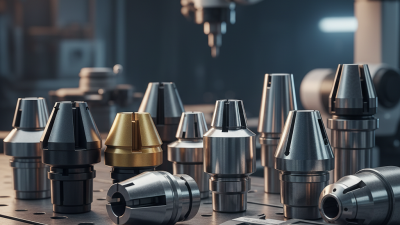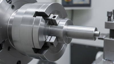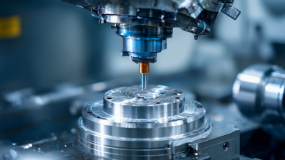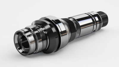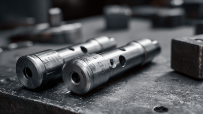
Choosing the right Pull Type Collet begins with understanding the machine, the material, and the workholding problem. A collet that fits one spindle may perform poorly on another. Taper angle, nose configuration, gripping range, runout, and bar diameter all influence the final result. Even a small mismatch can leave marks on the workpiece or reduce repeatability during long production runs.
Manufacturing engineer Dr. Tony L. Schmitz often emphasizes a practical machining principle: “A stable process is a measurable and repeatable process.” That idea applies directly to Pull Type Collet selection. The collet should hold the part firmly without crushing thin walls. It should also maintain consistent clamping force after repeated cycles. Check the machine’s spindle taper carefully. Then compare the collet’s actual gripping range with the material diameter, not only the catalog maximum.
Look at the details.
For example, a 20 mm steel bar may require a collet designed for that exact range, rather than a larger collet tightened near its limit. Coolant, chips, surface finish, and loading speed also matter. In practice, operators sometimes choose by price or availability first. That shortcut can create vibration, uneven tool wear, and rejected parts.
There is no perfect choice for every application. A careful decision balances accuracy, gripping force, durability, and changeover time. Record the results from trial runs. Question the first assumption. Then select the Pull Type Collet that performs reliably under real production conditions, not just on paper.
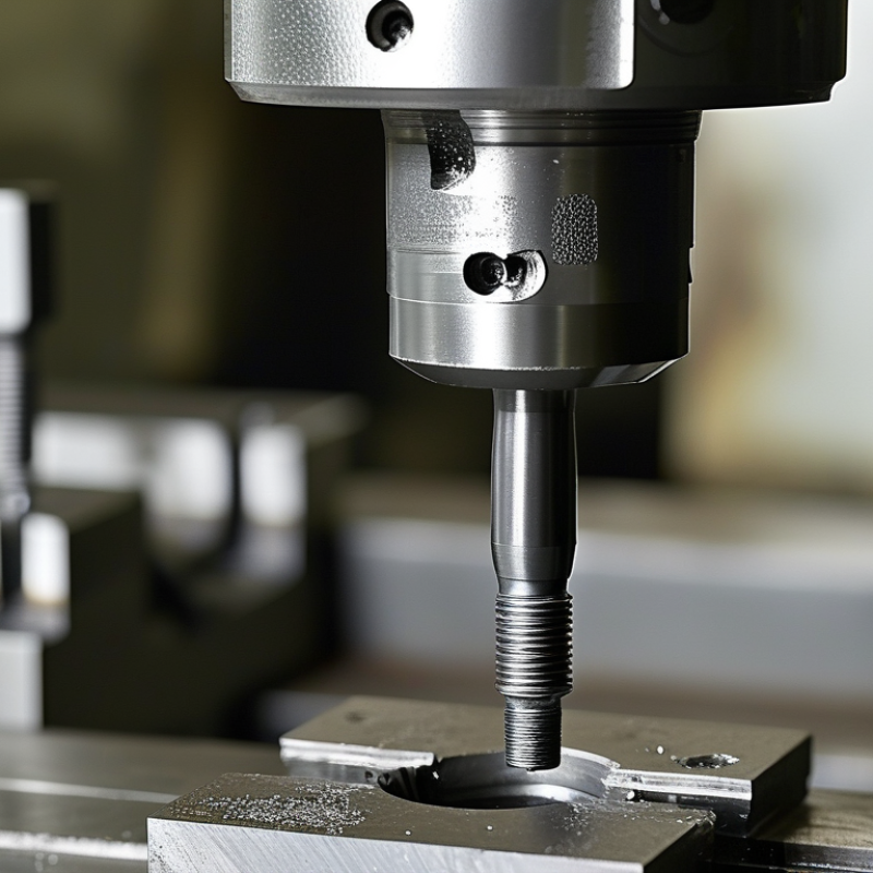
A pull type collet grips through axial movement. The drawbar pulls the collet into a tapered seat, forcing its segments inward. This action centers the workpiece while creating strong radial pressure. Taper angle, slot design, nose length, and bore size affect the result. A shallow taper can improve holding force, but it may release less easily. Small details matter.
In shop practice, select the collet according to the material diameter, shape, and machining load. A close bore fit usually improves concentricity. Excessive clearance can cause vibration and uneven marking. For bar work, the gripping length should support the part without blocking essential tool access. Thin-walled parts need controlled pressure. Too much force can distort them.
Check the drawbar stroke and available pull force before installation. The collet must seat fully and move smoothly. Clean the taper and contact surfaces carefully. Even a small chip can create measurable runout. Test with a dial indicator after tightening. Recheck it at operating speed when possible. A perfect selection on paper can still fail in practice. I would also question relying on nominal size alone; actual stock variation often changes the gripping behavior. Inspect slots, threads, and seating surfaces regularly, then replace damaged components before accuracy becomes unpredictable.
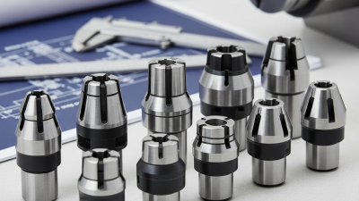
Choosing a pull-type collet starts at the spindle, not the tool drawer. Confirm the spindle taper, nose geometry, drawbar thread, and gauge-line length. A 7/24 taper collet must match the machine’s exact taper standard. ISO 15488 provides dimensional guidance for this collet family. Do not assume similar-looking tapers are interchangeable.
Match the collet bore closely to the tool shank. A 20 mm shank should use a collet designed for 20 mm, not a wide collapsing range. Measure the shank with a calibrated micrometer, then check runout near the collet nose. The 2024 U.S. Cutting Tool Consumption report recorded more than 2.6 billion dollars in annual tool consumption. That figure shows why a small interface error can waste expensive tooling and machine time. I have seen operators select by diameter alone. It seems practical, but it ignores taper contact and pull-back clearance. Check the machine manual, collet drawing, maximum speed, and balancing grade. HSK, BT, CAT, and other taper systems require different pull lengths and contact behavior. A collet can fit the tool yet fail at the spindle. That is the uncomfortable part. After installation, mark the gauge length and test a light cut before heavy production. Fresh measurements are safer than memory.
Match Collet Size and Taper to Your Machine Spindle
Select a collet family that covers the required workpiece diameter without exceeding its rated capacity. Confirm the spindle nose, locating features, drawtube connection, and nominal taper angle before installation. The dimensions shown are standard nominal capacities; always verify the machine and collet manufacturer’s specifications.
A pull type collet must match the workpiece shape, size, and machining demands. Round stock usually needs a standard round collet with balanced gripping force. Hexagonal or square stock requires matching internal geometry. Shape matters. A mismatched collet can mark corners or allow the part to rotate.
Measure the workpiece at the actual gripping area, not only from its drawing. A few hundredths of a millimeter can affect clamping stability. Choose a collet bore slightly below the measured diameter when the system allows limited collapse. Excessive clearance reduces contact. Too little clearance may prevent full seating and increase wear.
Consider the workpiece length and surface condition. Pull-back action can improve axial positioning, but thin-wall parts may distort under heavy pressure. For delicate tubing, use a collet designed for broader contact. For short parts, confirm that enough material enters the gripping zone. A step collet may help with shoulder locations, but it can reduce flexibility.
Chips inside the taper can create runout and false measurements. Inspect the collet before each setup, especially after interrupted cuts. In practice, published capacity ranges do not always reflect real holding performance. Tool pressure, material hardness, and surface finish change the result. I have seen a technically correct collet perform poorly because the bar was slightly oval. A short test cut, followed by a runout check, often reveals more than a catalog table.
How to Choose the Right Pull Type Collet?
A pull type collet should match the accuracy your operation actually needs. Check radial runout, repeatability, and the required gripping length. A clean, undamaged collet matters as much as its stated tolerance. Even a small chip can shift a workpiece several microns. Measure the setup at the tool and workpiece, not only from a catalog specification. I have seen excellent collets perform poorly because the taper was dirty. Perfect numbers can mislead.
Grip strength depends on pull-back force, contact area, and cutting direction. A longer gripping surface usually improves stability, but it may limit access to shoulders or recessed features. Thin-walled parts need controlled pressure. Excessive force can distort them before machining begins. Heavy cuts require firm support and balanced clamping. The safest choice is not always the strongest one.
Tips: Match the collet bore closely to the stock diameter. Avoid relying on full collapse. Test runout with a calibrated indicator. Inspect marks after clamping. If the part slips, review the setup before increasing pressure. Material compatibility also deserves attention. Hardened steel, aluminum, brass, and plastic respond differently to contact pressure. Choose suitable contact geometry and surface finish. Coolant, chips, and heat can change performance. One detail is easy to miss: a collet that grips softly during a dry test may behave differently during a long, heated cycle. Recheck it under real cutting conditions.
| Pull Type Collet | Typical Accuracy | Grip Strength | Clamping Range | Best Material Compatibility | Recommended Applications | Main Limitations |
|---|---|---|---|---|---|---|
| Standard Pull-Back Collet | Typically about 0.005–0.013 mm TIR when the collet, spindle, and workpiece are clean and correctly matched. | High and generally consistent because the workpiece is pulled against a locating surface during clamping. | Usually designed for a specific nominal diameter; practical compression is commonly limited to approximately 0.25–0.50 mm, depending on the collet design. | Steel, stainless steel, aluminum, brass, copper, and engineering plastics when the correct serration and bore finish are selected. | General turning, repeat production work, short components, and operations requiring reliable axial location. | Limited flexibility for widely varying diameters; excessive undersize workpieces can reduce concentricity and gripping force. |
| Dead-Length Pull Collet | Commonly about 0.005–0.010 mm TIR in a properly maintained high-quality setup; repeatability is usually better than with basic pull-back designs. | High radial grip with minimal or no axial draw-in, helping preserve part length and shoulder location. | Normally narrow and size-specific; use a bore matched closely to the workpiece diameter. | Hard and soft metals, particularly steel, stainless steel, aluminum, and brass where axial position is critical. | Precision turning, secondary operations, thin parts, and components with a finished shoulder or fixed length requirement. | Requires accurate workpiece diameter and proper stop design; poor fit can cause marking, slip, or reduced accuracy. |
| Step Pull Collet | Typically about 0.010–0.025 mm TIR, depending strongly on the machined step, seating condition, and workpiece geometry. | Moderate to high for parts supported by the step; less suitable when the exposed gripping area is short or irregular. | Built around a stepped or shouldered profile rather than a broad diameter range. | Steel, aluminum, brass, and plastic parts with a consistent shoulder or flange. | Flanged components, irregular profiles, castings, and parts that cannot be held securely by a plain round bore. | Usually custom or application-specific; the step must be accurately machined and matched to the component. |
| Expanding Pull Collet | Often about 0.010–0.025 mm TIR, with actual performance governed by the internal bore, mandrel condition, and wall thickness. | High for parts with a sufficiently rigid and accurately finished internal bore; not intended for weak or highly flexible walls. | Generally covers a small internal-diameter range; expansion must remain within the collet’s specified working limit. | Steel, stainless steel, aluminum, brass, and other materials with a stable internal bore. | Holding rings, sleeves, tubes, gears, and finished external surfaces that must remain free from clamping marks. | Can distort thin-wall parts; internal chips, burrs, or taper variation can significantly affect concentricity. |
| Emergency or Machinable Pull Collet | Approximately 0.015–0.040 mm TIR is typical after careful machining; it is not normally the first choice for maximum repeatability. | Moderate to high after boring or turning to the exact workpiece size. | Flexible after machining, but the usable range is limited by the amount of material removed and the remaining wall thickness. | Soft materials and non-standard profiles, including aluminum, brass, plastics, and low-volume steel components. | Prototype work, one-off parts, special shapes, and short production runs where a dedicated collet is not economical. | Requires an additional machining operation and may have lower service life or repeatability than a hardened standard collet. |
| Rubber-Flex or Soft-Contact Pull Collet | Typically about 0.025–0.075 mm TIR; accuracy depends on elastic recovery, contact uniformity, and the condition of the gripping surface. | Low to moderate, but sufficient for light-duty machining and cosmetic protection when cutting loads are controlled. | Usually accommodates a wider range than rigid precision collets, but clamping force varies with diameter and material hardness. | Delicate aluminum, polished metal, painted surfaces, thin-wall parts, glass-filled plastics, and other easily marked materials. | Finishing, inspection, light drilling, light turning, and applications where surface protection is more important than maximum cutting force. | Not suitable for heavy interrupted cuts, high torque, high heat, or applications requiring very low runout. |
Choosing a pull type collet starts with the machine, not the collet catalog. Verify spindle taper, thread size, drawbar length, collet capacity, and available pull-back clearance. The workpiece should enter smoothly, without force or excessive stick-out. Even a small diameter mismatch can increase runout and reduce gripping strength. ISO 230-2 provides methods for checking machine-tool positioning accuracy, but practical verification still matters on the shop floor.
Maintenance directly affects repeatability. Remove chips from the collet, spindle taper, and contact surfaces before every setup. Do not force debris deeper with uncontrolled compressed air. The U.S. Department of Energy reports that compressed-air leaks can waste 20–30% of compressor output, so clean, regulated air is both safer and more efficient. Inspect the collet for bell-mouthing, damaged threads, rust, or uneven spring slots. Replace questionable components. A clean setup can still drift. I have seen operators blame the tool when the real problem was a worn taper or incorrect drawbar torque.
Tips: Measure runout at the collet nose and near the workpiece. Record the reading. Keep stick-out as short as clearance allows. Use a calibrated torque wrench, then recheck after the first production cycle. Store collets in protective sleeves, not loose in a drawer. Maintenance intervals should follow the machine maker’s guidance and actual cutting conditions; a dusty, high-cycle shop may need shorter intervals. Perfect routines are rare, but documented checks expose weak habits.